First Prototype
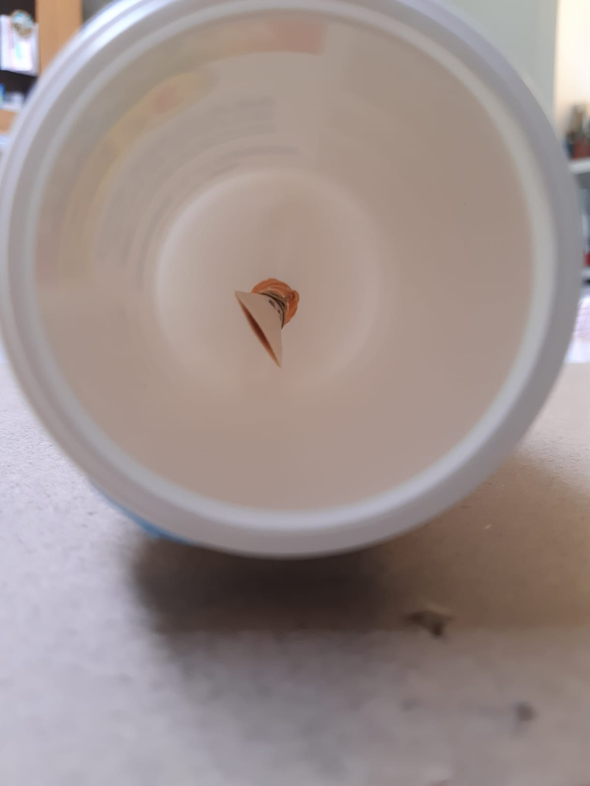
Using a simple plastic jar that I had at home, I pierced the bottom, and I inserted a straw on which I placed the reed. By holding the jar to my mouth and simply blowing, the reed started to vibrate. This first prototype served as a demonstration of the concept and as a first example to think about what the difficulties would be to be faced.
Second Prototype
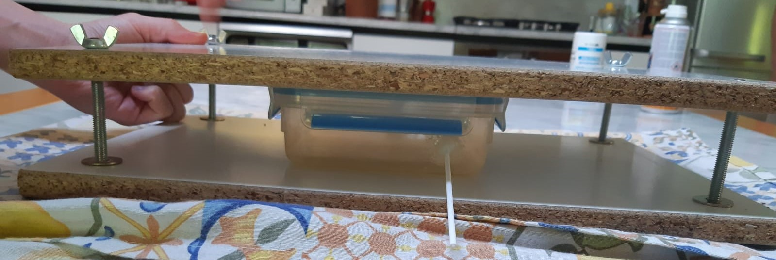
I used a food container with an airtight lid as the base for the second prototype. I made two holes. One for a straw and reed, as in the previous version, and the other to insert a tube of a compressed air can, generally used for cleaning electronic equipment. I began testing the pressure tightness of this prototype and it quickly became clear that maintaining an airtight seal was a difficult challenge. Generally, lids are designed to prevent seepage from the outside to the inside. In my case I had pressurized air pushing outward and rendering the lid completely useless. So, I used silicone around the straw and air hose of the can to prevent any kind of leakage from those points and set about finding a solution for the lid. I inserted the box between two wooden boards using long screws and bolts to fix the lid under a strong pressure. With these measures the prototype worked, albeit with some leakage, but I needed more space and more transparent walls.
SAFETY VALVE
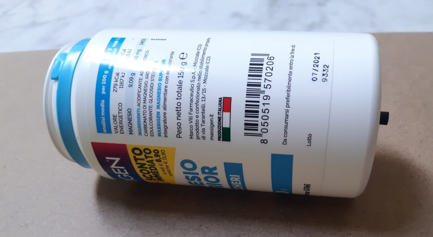
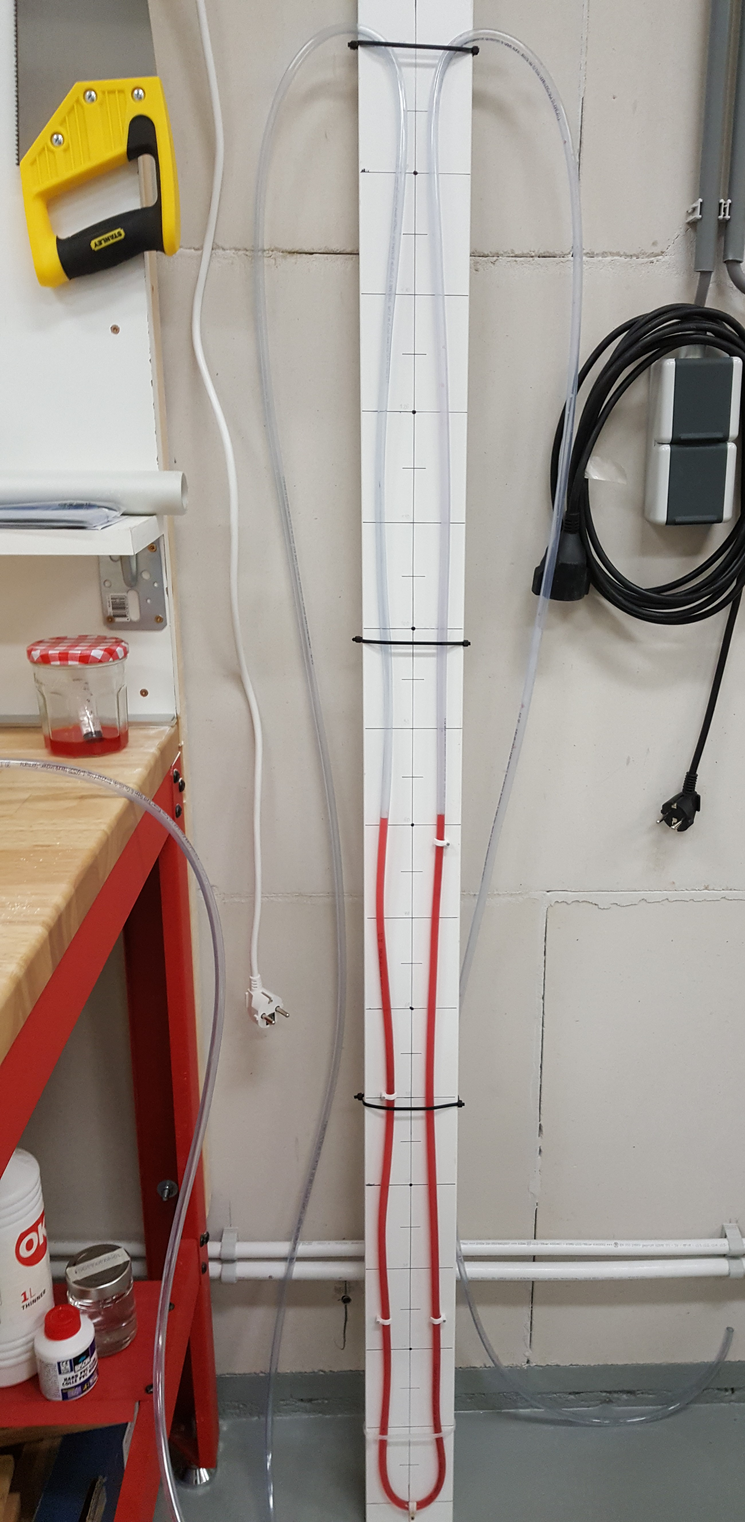
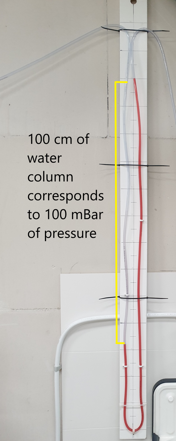
To prevent further prototype explosions and to provide a form of safety for myself and anyone working with the box, I decided to include a safety valve. This one has a very simple, but effective, operation. It consists of a U-bent rubber tube attached to a 150 cm vertical wooden rod. I then connected the pipe half filled with water to the box. As the pressure in the box increases, so does the pressure acting on the water in the side of the hose in contact with the box. Each mBar of pressure added in the box can press down the water column by 0.5 cm. As a result, the water column on the other side of the pipe bend will increase by 0.5 cm. This difference that is created between the two water levels of 1 cm confirms to me that inside the box the pressure has increased by 1 mBar compared to the external atmospheric pressure. Since the rod, and therefore the water column, is 150 cm, the maximum pressure limit is 150 mBar. In case the pressure by mistake should be higher, the water would be pushed out of the pipe. This would create an air vent and instantly the pressure in the box would be reduced. The compressor cannot create enough airflow to generate pressure in the box if both the reed hole and the relief valve hole are open at the same time, and this ensures that the pressure in the box cannot exceed 150mBar. To make the water level more visible, I added drops of food coloring. I marked the centimeters on the wooden rod so that I could use the water level as an additional measuring tool along with the pressure gauge to measure the pressure in the box.
AIR CONTROL
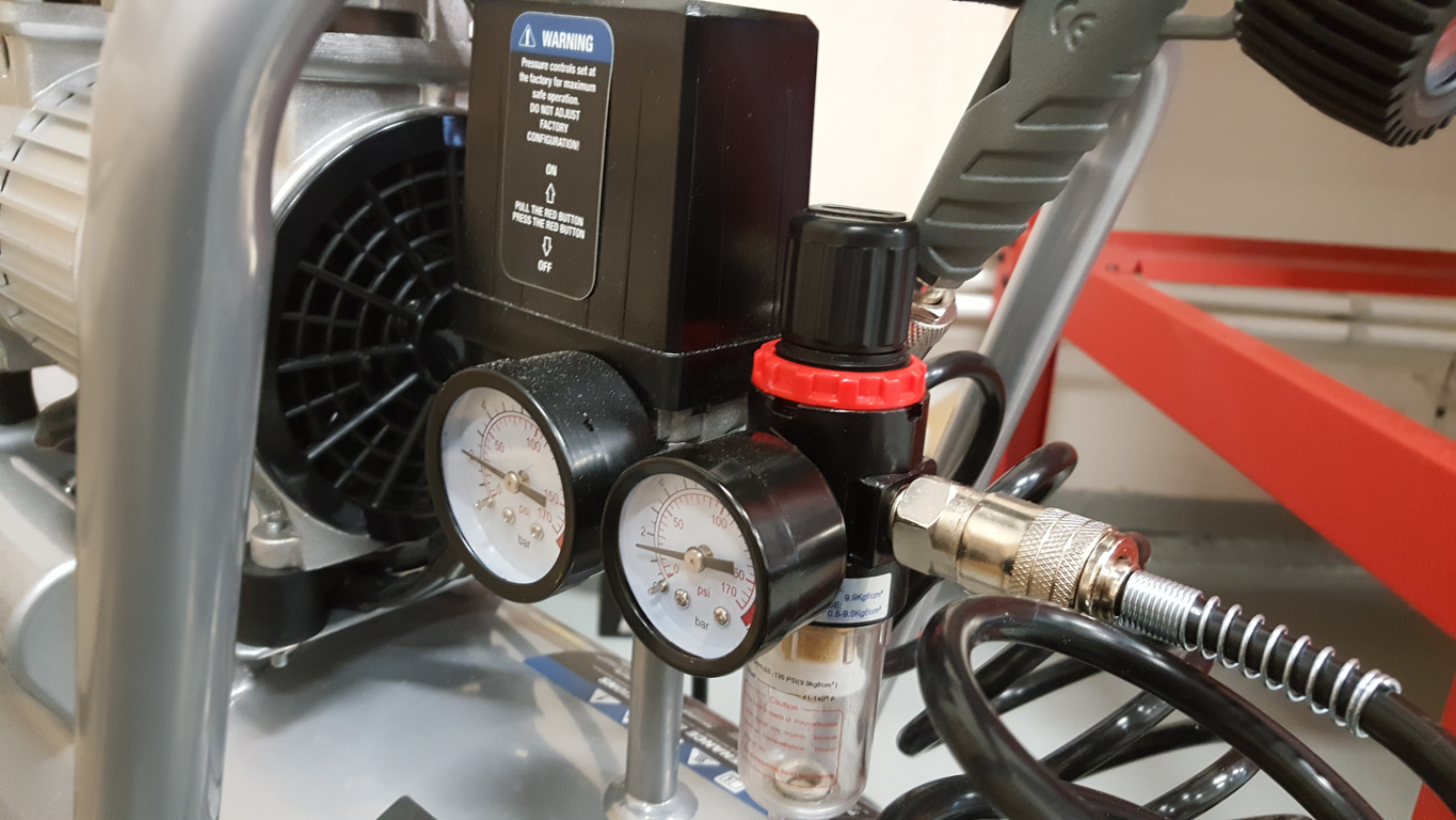
In order to obtain the desired images of the reed in vibration, it is essential to be able to generate a steady, adjustable flow of air through the reed. Under normal conditions the reed is set into vibration by the bassoonist's breath. However, in my case I needed a longer lasting and, above all, more stable source. In order to shoot, it was necessary that the reed was in vibration for several seconds, and to repeat this experiment several times, even with different reeds, the human breath was not reliable enough to reproduce the same conditions. Choosing to use a compressor put me in a position to create a constant flow of air through the reed for a time that was comfortable for my shooting. One of the problems that arose with using a compressor is that it is designed to work at pressures that are too high, up to 10000 mBar, while human lungs can create a pressure of 150 mBar at most. With a commercial pressure reducer, I was able to reduce the maximum air output pressure of the compressor down to about 500 mBar. To further reduce the pressure, I used a needle valve generally used for LPG cylinders. It is important to note that the tap only adjusts the airflow out of the compressor and not directly the pressure. If the box were completely closed, the pressure would over time reach the same value as the pressure reducer regardless of how much the tap is open. Therefore, the box is not completely sealed, but it does have an air outlet. By placing the reed over this one exit hole, air is forced through the reed thus putting it into vibration. To achieve a constant pressure inside the box, between 50 and 150 mBar, I needed to create a balance between the amount of air going in and the amount of air coming out through the reed.
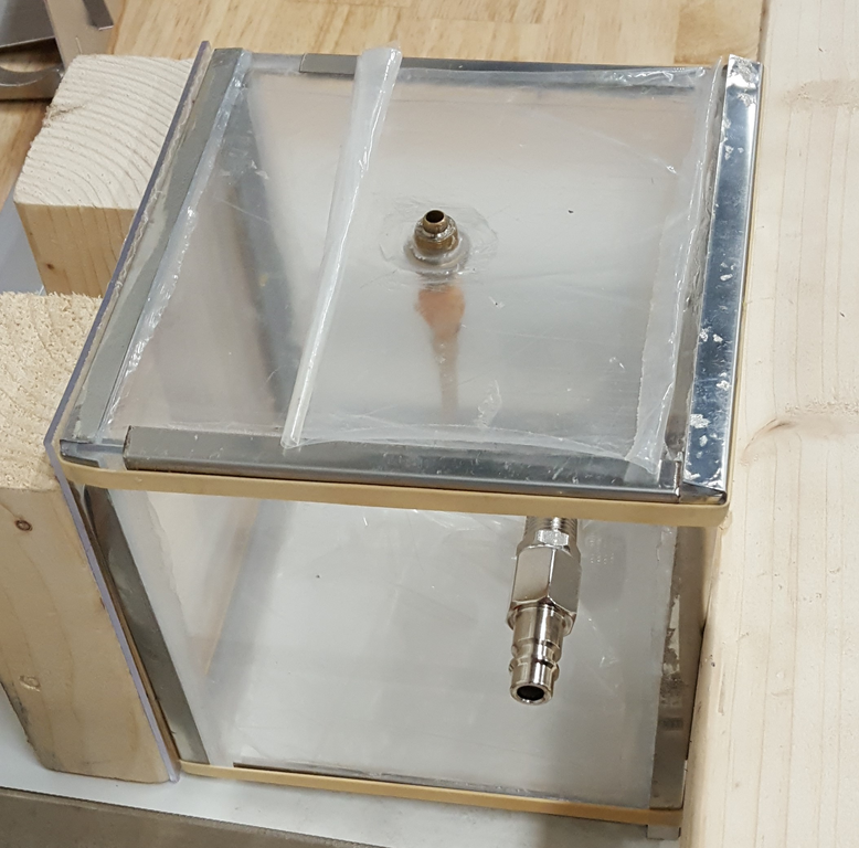
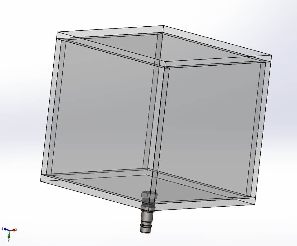
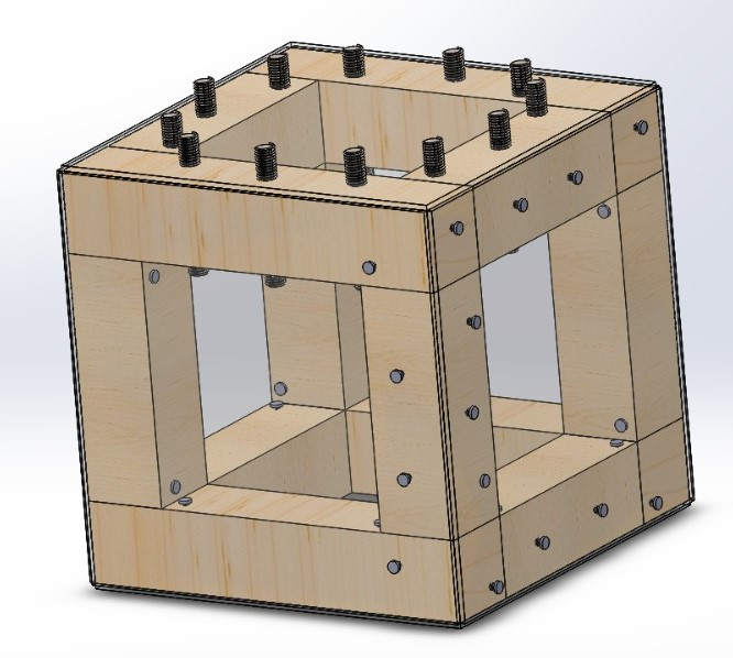
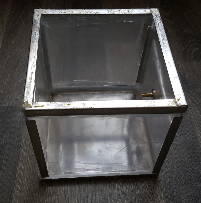
Fourth Prototype
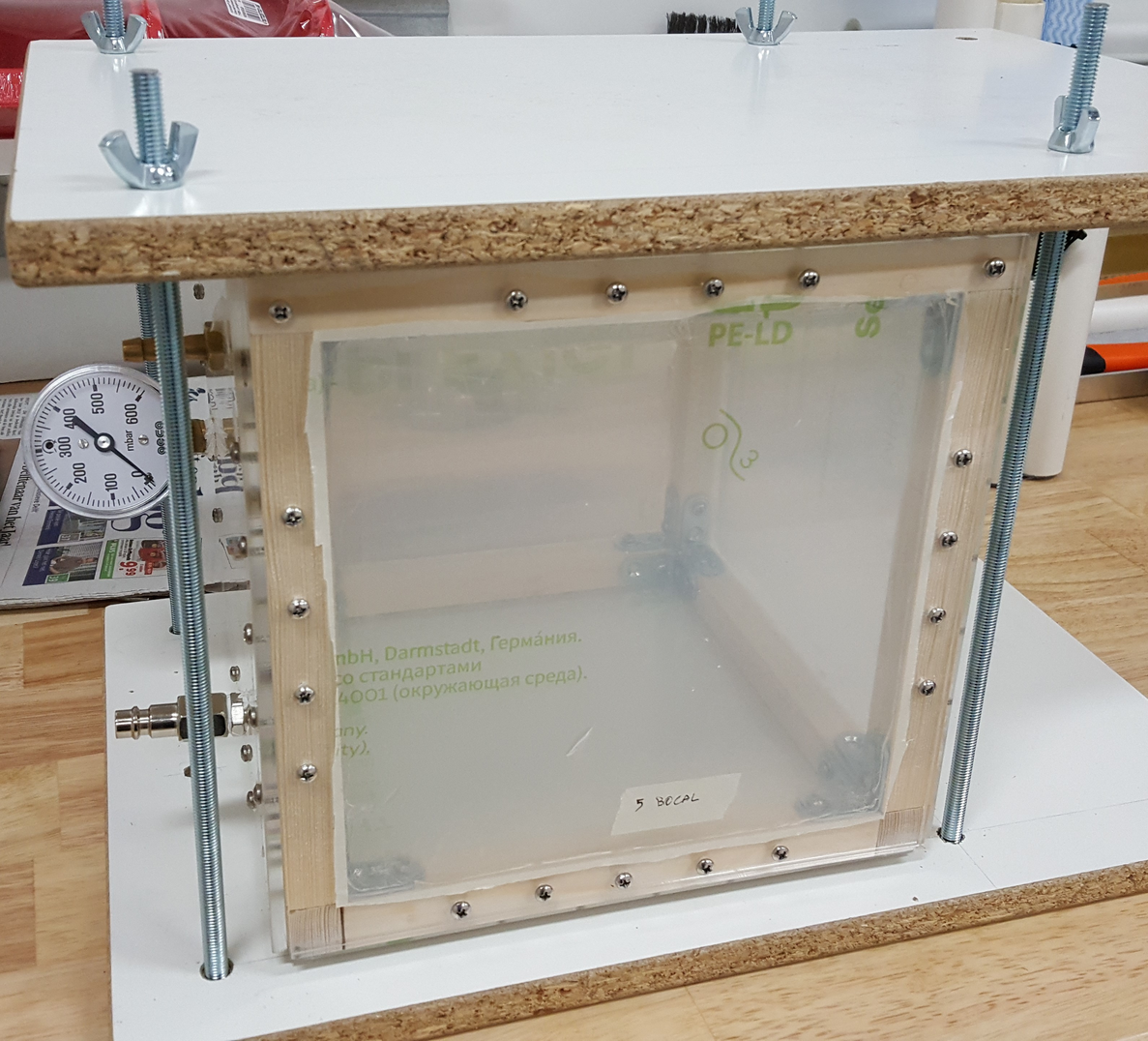
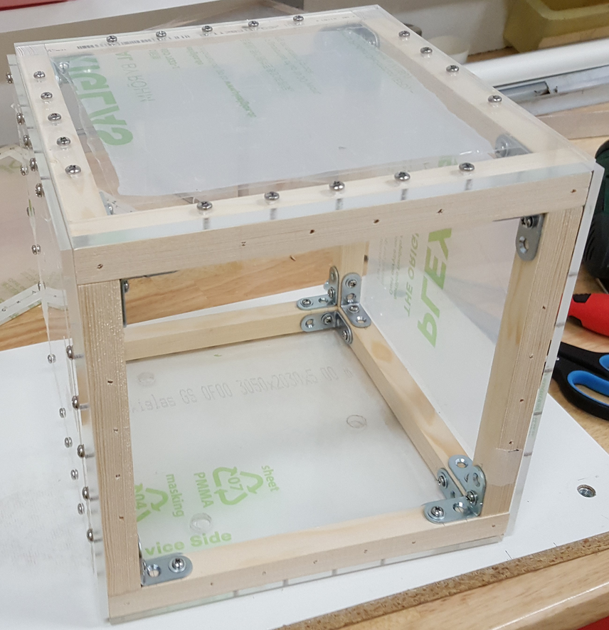
Doing some quick calculations, the 23.6x23.6x23.6 cm box of the fourth prototype would have to withstand a pressure of about 40 kg per side. I therefore decided to build a 1.8 cm thick wooden frame to create a solid skeleton. I then reinforced it at the vertexes with metal ells. I then purchased six 0.6 cm thick Ultra Resistant Plexiglass facades that would be able to withstand the required stress. I then drilled four holes: the first for a bassoon Bocal where I would then put the reed, the second for the compressor inlet connection, the third for a pressure gauge to measure the pressure in the box and the last for a safety valve that I explain later how I made. The lid was once again the most complex part to solve. In my initial design for this prototype, I had planned to use several screws and bolts on the front of the lid in order to press it down with a force distributed across its entire profile. However, for fear that the wooden structure could become too fragile with all those holes, I opted for the system already tested earlier with the second prototype: two wooden boards held in pressure by long screws and bolts to cage the box. However, the problems were not over, every time I put pressure on the box I had numerous leaks, so that I could not create the pressure necessary to put the reed into vibration. After several attempts I finally managed to seal the leaks along the sides with a large amount of silicone placed on all internal sides. But the lid remained the weak point. I tried various materials as a gasket but with little success, until I found a tape generally used for window frames. With these new solutions I was able to achieve and stabilize the pressure with minimal leakage. The box was finally finished.
During filming, however, the lid proved to be a difficulty. Its opening and closing took a couple of minutes and with the need to change the reed several times the operation started to become annoying. Seeing me in difficulty, the engineer Jaap Wijsman built and then gave me an improved version of the lid. The base of the lid remains the same as my version, but he added a circular opening in the middle with a screw cap that is just the right size to fit a hand through. You can now access the box in just a few seconds.
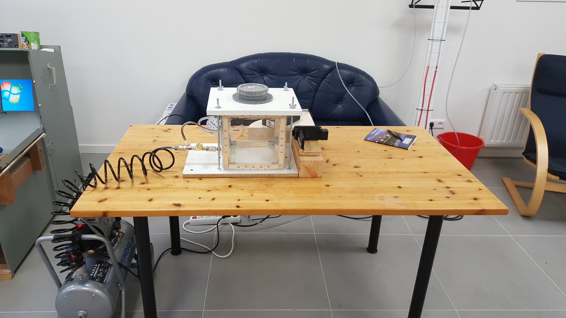
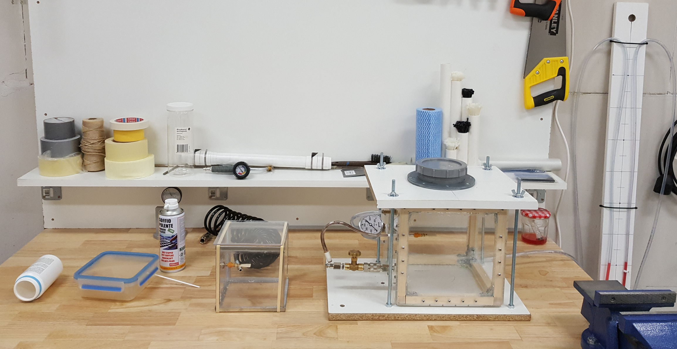
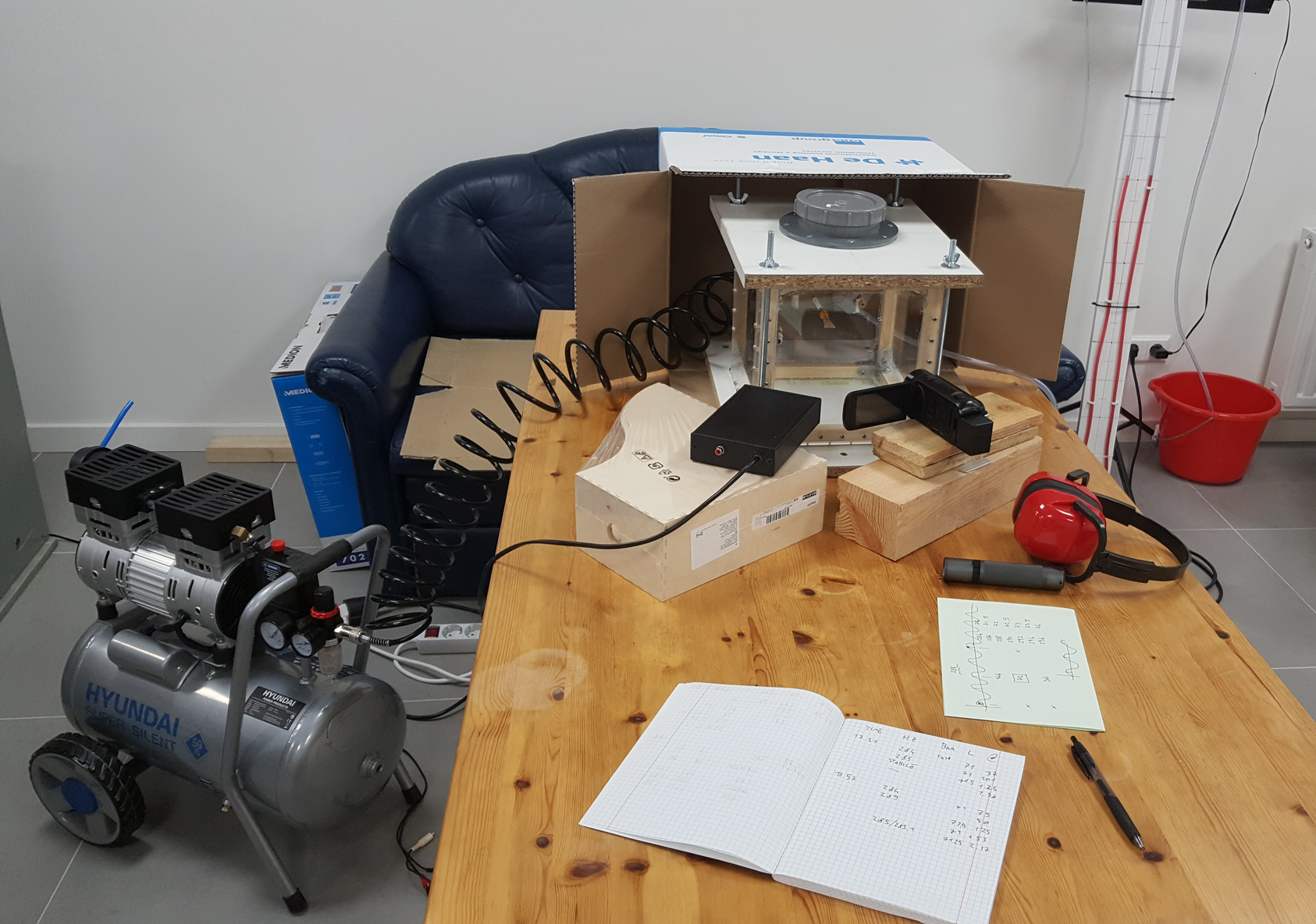
SETUP
The reed observation setup consists of four main parts: an air source, a pressurized observation chamber, a safety valve, and a video camera with a strobe light.
Third Prototype
I decided to build the box completely from scratch using six walls of 2mm thick plexiglass and aluminum L-segments to give structure to the edges. Using special glue, I created a 15x15x15 cm cube. I then prepared a support for the reed by modifying a graft of a compressor. I then drilled two holes and glued the support and a compressor air inlet fitting. To solve the lid problem, I tried gluing rubber bands as a gasket and holding it firmly to the box using some wood and clamps. In one of my first pressurized tests, I accidentally fed air into the box at too high a pressure. With a loud and quick whistle of the reed, the box exploded. The idea worked, but I needed a lot more structural strength and some sort of safety system to prevent further explosions.
PRESSURIZED BOX
In my intentions the reed observation chamber was to be a box capable of maintaining the pressure necessary to create a flow of air to set a reed into vibration and allow for easy shooting.
I then proceeded experimentally to create a series of prototypes that I then tested to improve or correct the next version.
The final box had to have these characteristics:
- ability to hold air under pressure
- air outlet with a support for the reed
- air source inlet
- removable lid to allow testing of multiple reeds
- transparent walls for filming inside
- possibility to measure the internal pressure
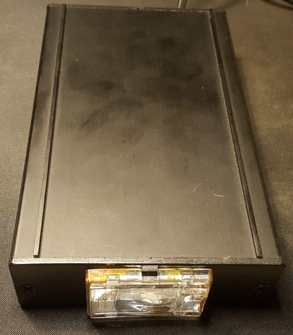
STROBE LIGHT
A strobe or strobe light is a light that can pulse at very high frequencies and create short but very intense pulses of light. When used in conjunction with a video camera, it is possible to create intermittent video where the image is interspersed with quick moments of light and darkness. Using this technique in situations of continuous and periodic motion you can create a slow-motion effect. This is called the strobe effect. A typical example of such an effect are videos of helicopter propellers that appear completely still while the helicopter is in flight. A video is nothing more than a sequence of images captured in quick succession. The reason why the blades appear stationary is that the rotation speed of the helicopter's rotor and the shutter speed of the camera coincide perfectly or are one the exact multiple of the other. In fact, the camera is creating a series of images of that helicopter while the blades always return to the same position thus creating the illusion of stillness.
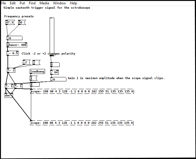
By providing the reed with a constant flow of air its vibration behaves as a regular and periodic motion, thus making it possible to exploit the stroboscopic effect. In my case I was not looking for a static illusion effect, but rather a slow-motion effect. By listening and measuring the pitch at which the reed is vibrating it is possible to determine the frequency of its vibration. If you set the strobe to the exact frequency or to a multiple of the reed's frequency, the image obtained by the camera is static and no motion can be recorded. However, if instead of exactly a multiple you take a close number of even just 0.1Hz away you can capture the motion of the reed every time in a slightly advanced position. I was thus able to create the desired slow-motion effect. Prof. Peter Pabon helped me in my project by providing me with an oscillometer and creating a patch in PureData to be able to configure the strobe from the computer.
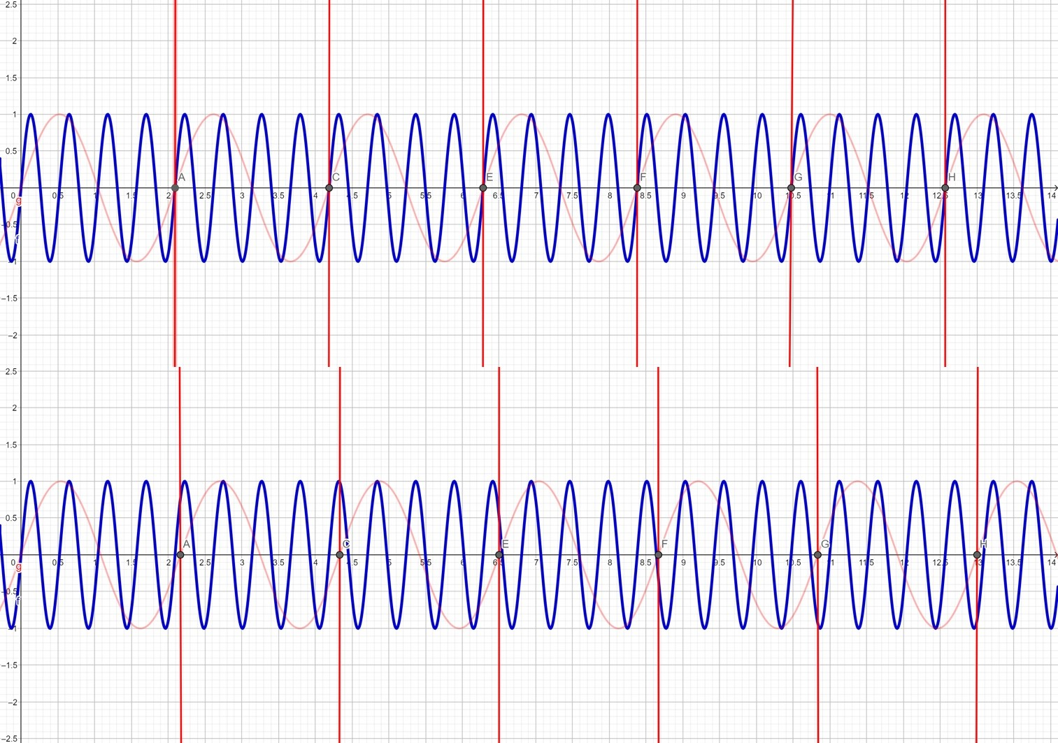
graph showing the difference between the frequency of vibration of the reed (in blue) and the frequency with which the strobe light emits its flashes (in red).
Above shows how a static effect is achieved.
Below shows how a slow motion effect is achieved.
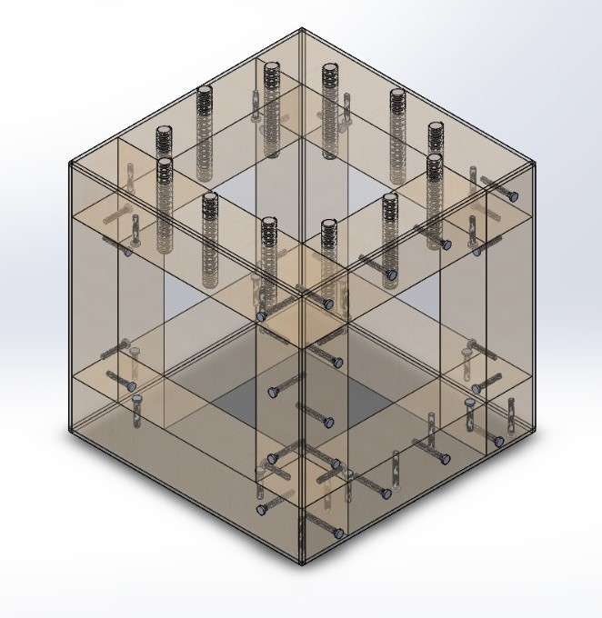
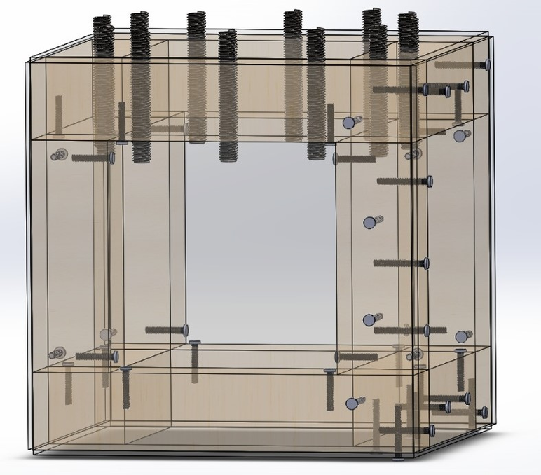
3D project of the Fourth Prototype. Trasparency on to have a better view of the locations of the screws and bolts.
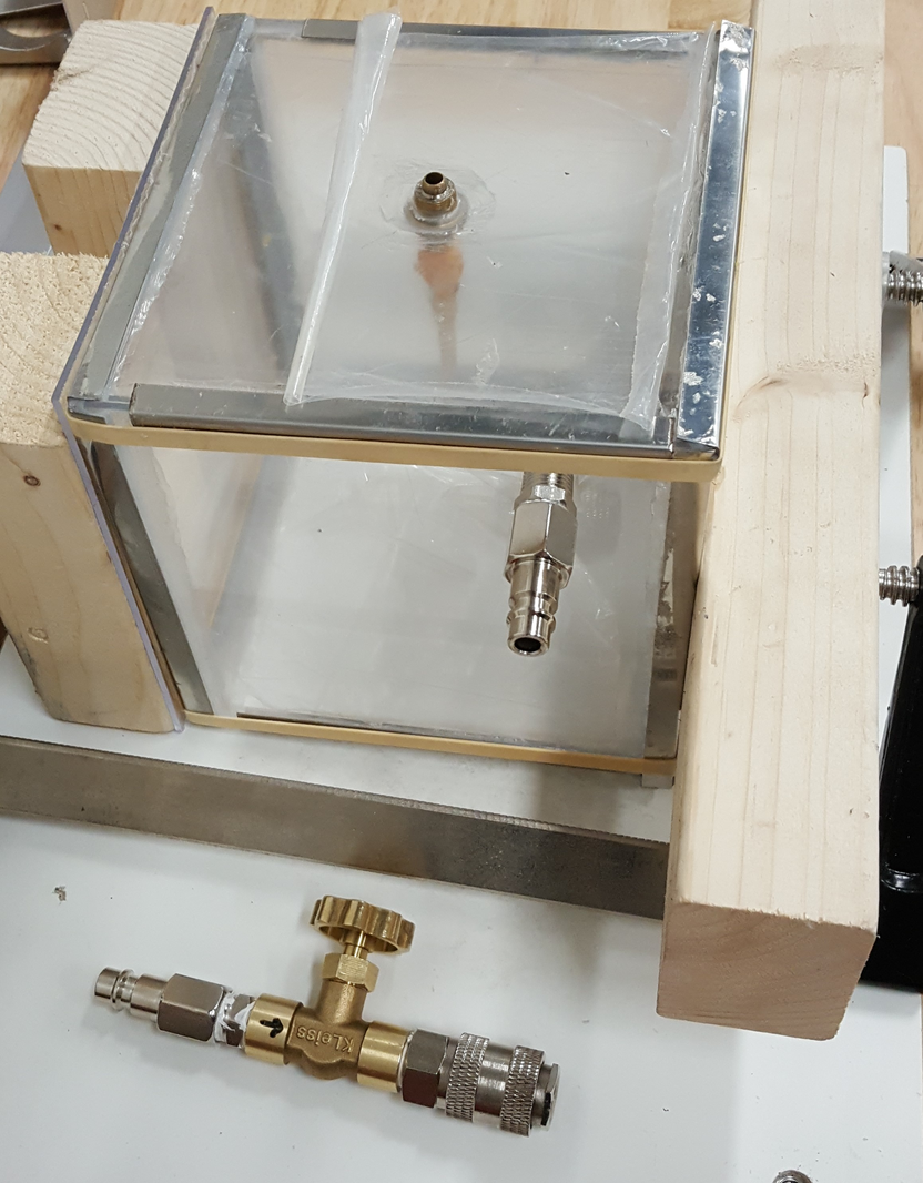
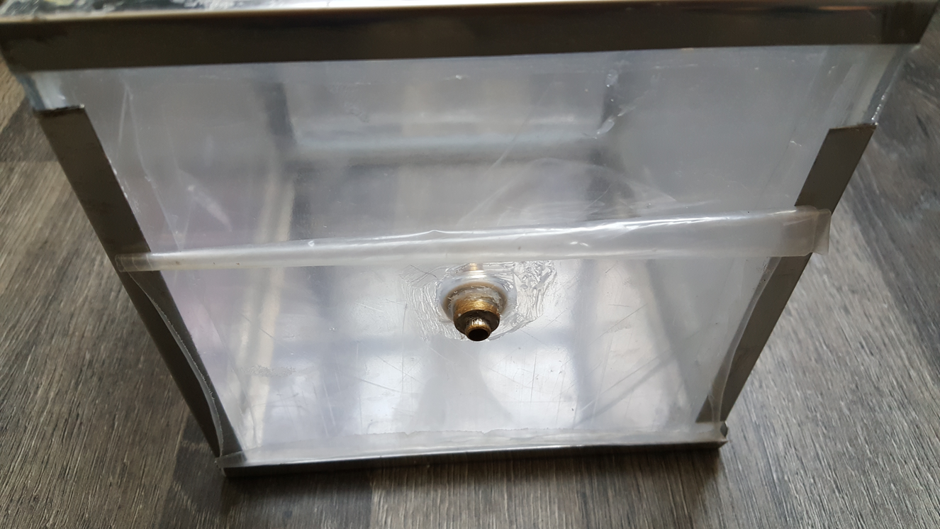
Regulator valve on the bottom and one of the pressurized box in the center with a view to the air intake connector.
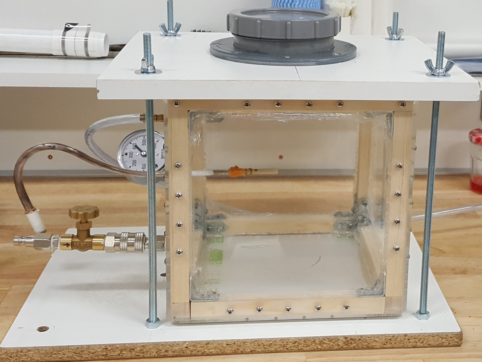
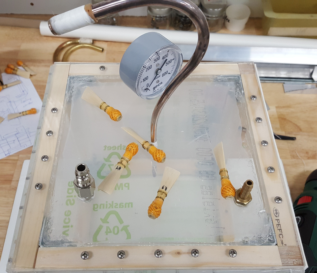
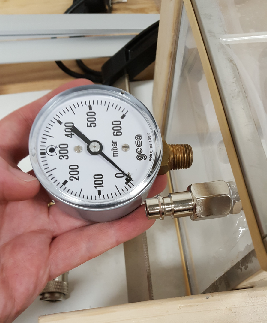
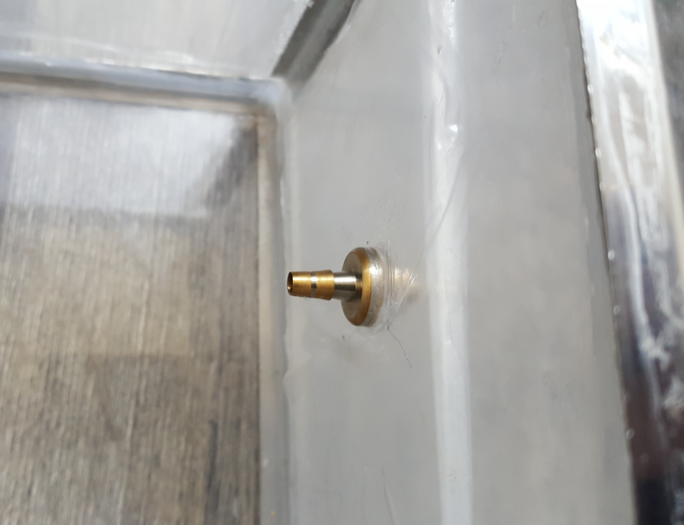
Detail of the air intake, the safity valve connector, the pressure gage and the bocal on the Fourth Prototype