The XT-Press was built in MDF wood and PVC pipes from a process that can be divided into 3 phases, namely: parts research and fabrication, press assembly and test printing and press refining
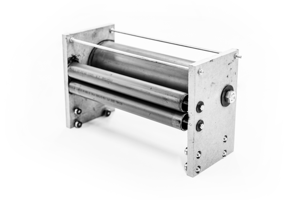
Two types of bearings were coupled. Some to fit the printing cylinder and the ink rollers and others that serve to direct the print-head movement, these are external to the piece.
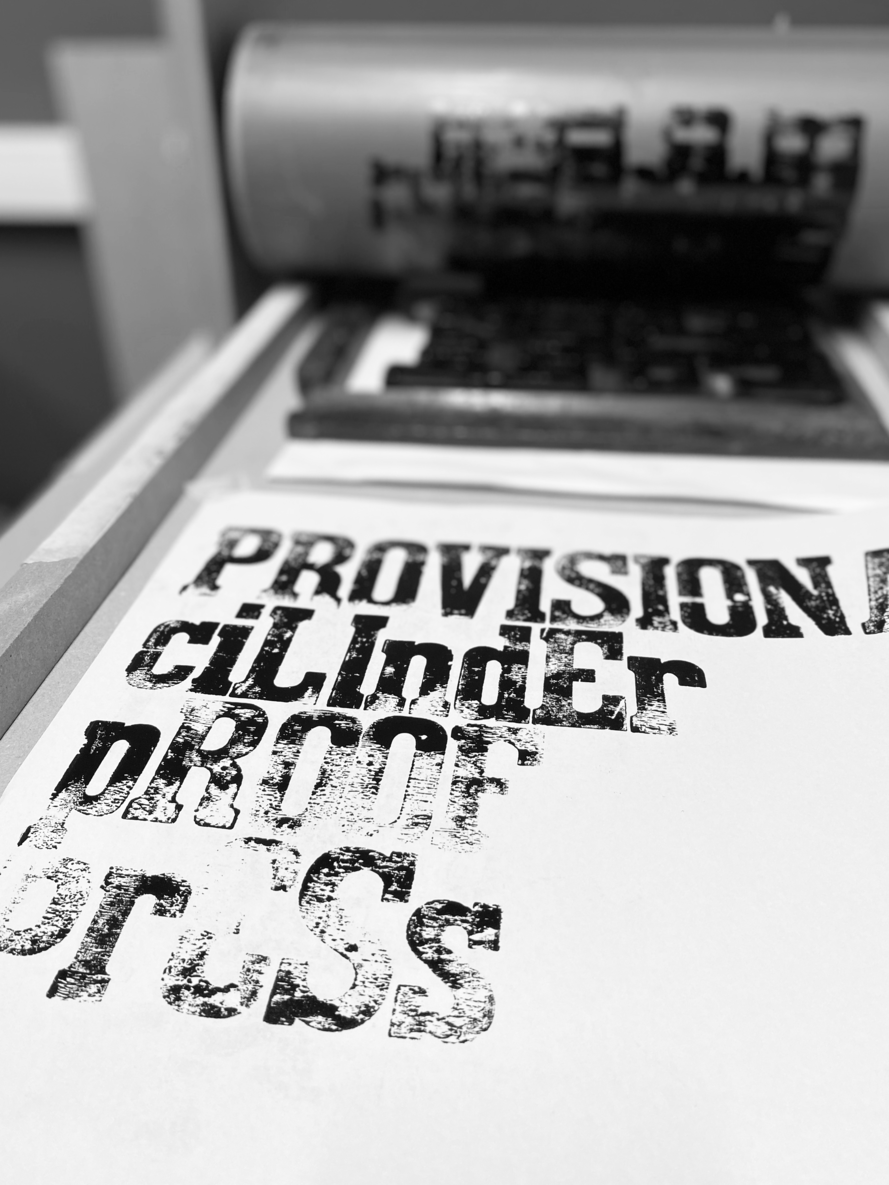
In addition, two Xcm wide parts of a PVC pipe with Xcm diameter, and other Xcm wide part of a Xcm diameter tube were used. The two tubes of the same diameter were used as ink rollers. The larger diameter tube was used to build the printing cylinder of the “provisional cylinder proof press”.
Bearings, screws, nuts and parts made from 3D printing were also needed to build the press parts. These materials were purchased in a bricolage/construction materials warehouse. Preference was given to the most standard sizes — eg. the diameter of the threaded rods to fit / compatible with the bearings.
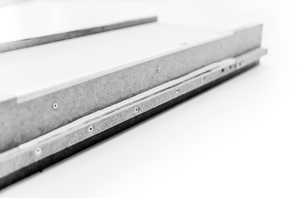
From these materials, the main parts were built. The printing base was assembled from the MDF pieces that were glued and screwed. The gutters, through which the ink rollers and the printing cylinder move, were also built with MDF. From 19mm MDF thick pieces glued together, the gutter was built in two levels for the back and forth movements of the cylinders. One of the levels is linear and the other has elevation and slope sections.
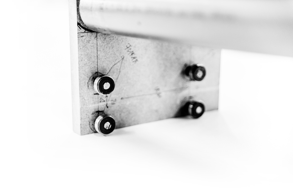
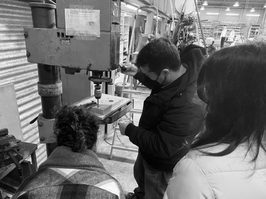
The print-head started from the MDF parts where holes were made to fit the bearings from hand-held and bench drills.
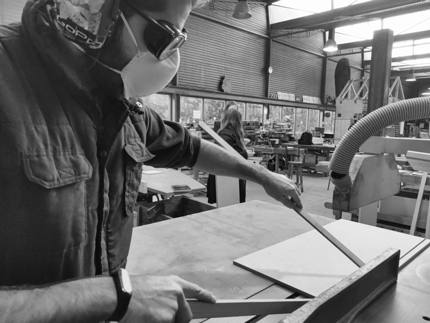
Parts research and fabrication
For phase 1, one MDF plate were used. They were pre-cut in the store in X parts. These were cut into X pieces to form the structure of the printing base, the gutters belonging to them and also the support for the cylinders. For that, It was necessary to use a table-top saw to cut the fine pieces for the rails. It is worth noting that this process can be accomplished with simpler and more affordable tools, aided by fablabs and even made from 3D printing.
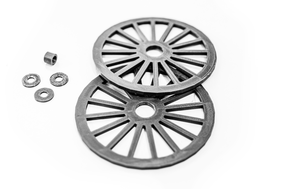
The printing cylinder and ink rollers, in turn, in addition to starting from PVC tubes, also received iron rods inside which 6 round pieces made in 3D printing with the same diameter as the inner part of the PVC tubes were placed. These parts were designed to support the PVC tubes, since the material is slightly malleable. In lack of specialized cutting tools, eg. a laser cutter, these parts were produced on an Elegoo Mars FDM 3d Printer with ABS plastic filament.
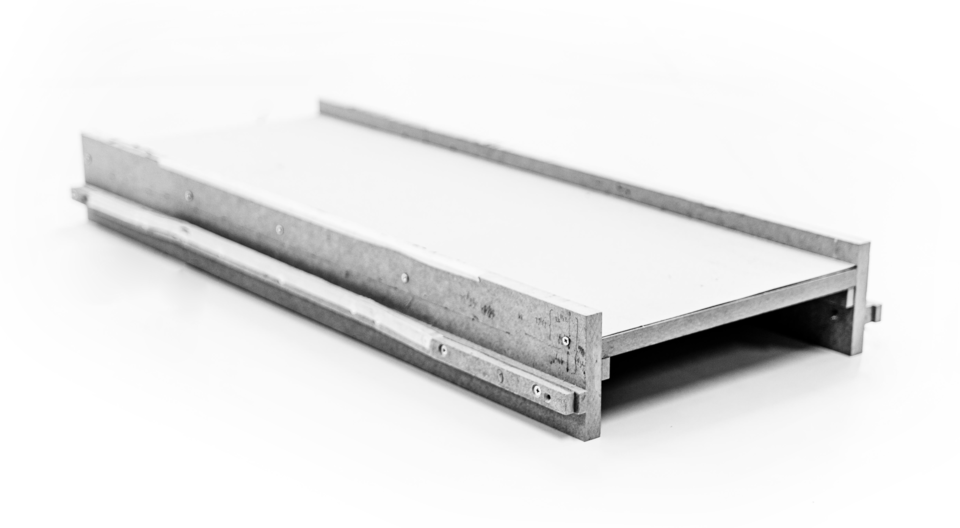
Next, the gutters were attached to the printing base with glue and then screwed down.
An important issue to be aware of is the precision of the assembly of the gutters — in a DYI / home environment one has to take into account some deviation in the drilled holes. Hence the gutters have to be assembled after the printhead is complete. Their position is defined by the inner bearings on each islet.
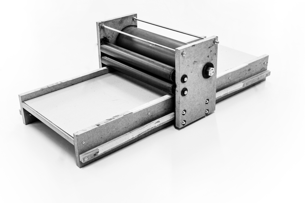
Finally, the print-head was connected to the printing base from the fit between the bearings and the gutters.
Press assembly
With the parts, phase 2, press assembly, began. Starting with the printing base, which underlay the width of the XT-Press, the print-heads were mounted. The printing cylinder and the ink rollers were fitted to the print-head with the bearings.
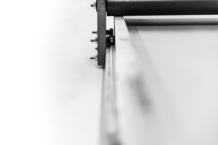
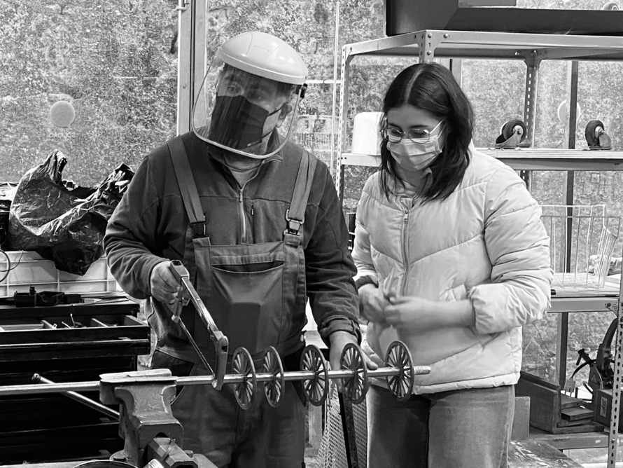
It was further noted that the screws holding the inner bearings of the print-head islets support had a very high head— which had no tolerance in the normal and raised position of the gutters while shifting their position. Thus, they were trimmed with an angle grinder (stone grinding wheel) until the heads were flat.
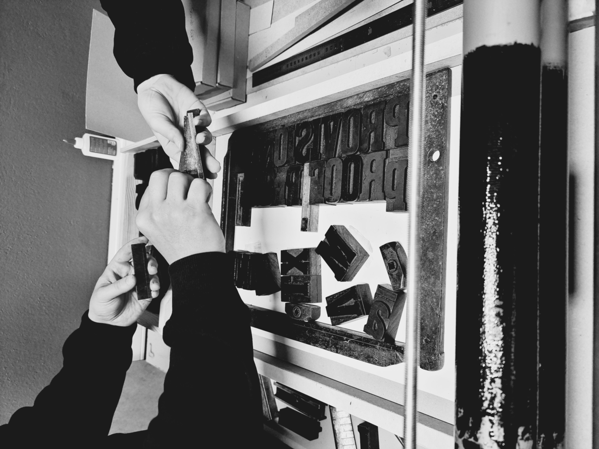
With that, the printing cylinder and ink rollers were again connected to the print-head and fitted to the printing base. In order to test the functioning of the XT-Press, some compositions were made with types of wood, as shown in the images below.
Test printing and press refining
With the press assembly, some inconsistencies were noticed that were corrected in phase 3, test printing and press refining.
First, it was seen that the gutters were slightly low. With that, the ink rollers touched the printing base, which was not foreseen by the project. Therefore, to correct the height, 3 layers of cardboard 1mm thick were used. The layers were glued at the level of the gutter with elevation and slope with glue and were finished with tape for the best movement of the bearings.