XT-Press Concept
Similar to the core ideas of most of the projects described in the previous state-of-the-art section, the aim of this research project is to design, develop and test the use of a custom-designed provisional press in the context of editorial or graphic design. This means that the equipment has to “respond” to the main target audience's needs and expectations: it has to be simple to build and operate; it has to focus on the speed of reproduction of multiples; it has to provide a minimal precision, and the capacity to print editorial impositions.
In other words: to conceptualize, design, and test a custom “Vandercook-style” self-inking flat-bed cylinder provisional proof press.
This press should be able to be employed easily (transported, operated) in educational contexts without a fixed room or place (due to the constraints of the Faculty spaces). Hence, the initial requirements were:
- To be able to be constructed using low cost and “over the counter” materials;
- Simple enough to be understood, built & operated by non-specialists;
- Robust enough to be put in use within academic editorial or graphic design contexts.
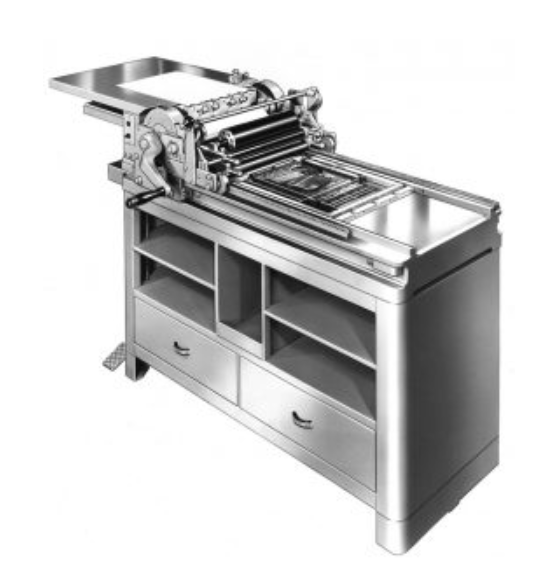
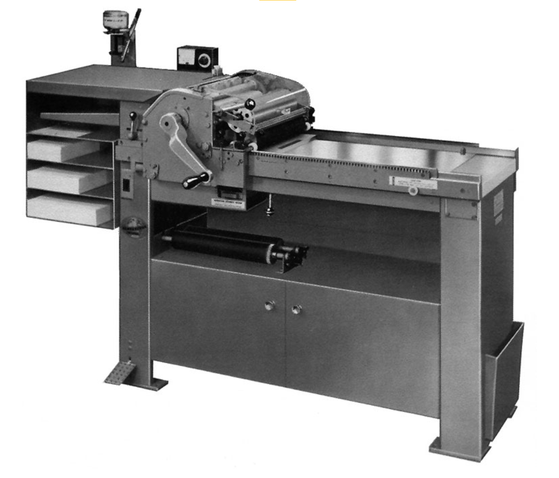
Bearing this in mind, we’ve set out to create a DIY provisional press replica of one of the most prolific printing presses — the Vandercook Proof Press. Specifically the capacity for self-inking and a large flat printing bed that easily accommodates editorial spreads, and ease of use of the model 4 Proof Press (from 1935), or the later SP15 (from 1961) specifically targeted for manual and hand-made tests (Vandercook Press, N. D.).
Using a hybrid printing head design from F-Press and the Provisional Press (Figure X)
Figure X – Printing head design adaptation. The embedded rollers and PVC-based cylinder design were maintained from the Provisional Press, despite the design being simplified and position guaranteed by nuts, and the cylinder diameter increased. The squaring of the islets of the print head was simplified by the use of simple threaded rods similar to the F-Press.
The print head design also included a simplified self-inking mechanism, using two PVC-rollers, with the mechanics based on the Vandercook Presses.
Finally, the press was designed to produce “large” print runs with a minimally accepted printing precision. This meant adapting the lift-return mechanism for the printing cylinder from the Vandercook presses. The Vandercook print head mechanism allows for the print cylinder grippers to hold on to the paper as it is being carried and printed on the form on the bed. And, afterward to release the paper and for the whole print head to return to its original position without over-inking the form as it returns, nor imprinting the form on the cylinder. (figure XX)
Figure XX – Vandercook printing operation. Paper grippers and paper. Print-head form inking (rollers) and printing (cylinder). Paper release. Safe (non-inking/printing) “safe-return” to the original position (attention to the 4 bearings?)
It meant designing simple to build and operate rail track and print-head islets modification to allow this “safe return”. To this design, we had to modify the rail tracks (underrails/under gtutters?). The F-Press and the Provisional press use simply underail roller mechanism, as they maintain the pressure in forward printing and backward return motion from the printhead.
In this [vandercook] design, the return motion of the print head has to be done on a “safe” lifted position of the printing cylinder — maintaining it clean to feed a new sheet of paper on the next run. Hence the “rails” were designed with two positions: a lowered printing position; and a lifted “safe-return” position (figure XX). In order to allow the shifting of these positions, the rails have three sections. The initial “parking” section, where the paper is fed on the cylinder, and to where the print head returns in the end. The main “print-return” section corresponds to the active area of the press. And the final “parking” section where the printed paper can be released and retrieved before returning the printhead to the initial position
Figure XX – positions and sections of the rails → falar nos slopes
In the parking sections of the rails, the printhead can be shifted to the printing position (to the left on the initial section) or to the safe-return position (to the right on the final parking section) by a simple manual operation. As an unexpected outcome, the use of the rail ramps allows for the release of the printed paper proof from the cylinder with a slight return movement. As it happens on a Fag Proof press.
Design issues found
Falta de esquadria (a printhead mexe-se e dificulta percorrer as calhas) → desenhar uma guarda intermédia → avaliar problemas de aumentar a largura da coisa
A distribuição de tinta no PVC → colos assimétricos → testar materiais mais macios e comprimir mais a ação dos rolos
Desenhar um sistema de grippers → para já fita-cola dupla?
Addressing all these issues will increase the complexity and costs of building the presses. They will have to be evaluated and cost-benefits pondered
Falar da escolha dos materiais : como foi feita e porquê?